Output transformers and push-pull stages.
This is a simplified approach, just to explain how it works.
The principles and calculations are basically the same for a push pull stage as it is for an SE stage, so everything described in the Impedance matching of loudspeakers to output valves article are valid for any transformer, but there are other concerns to be taken when calculating a push-pull transformer. However, let me take a little look at the calculations and the transformer, before we look at the output stage itself.
To use the formulas to calculate transformers it is important to remember that an output transformer has no impedance in itself; it reflects the impedance and any resistances on the secondary side over to the primary side and thereby present an impedance as a load to the output valves.
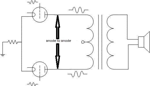
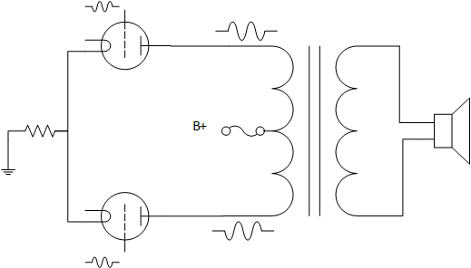
The load to valves connected as a push-pull stage is always specified as “anode to anode” (Zaa) illustrated in the drawing below. And since B+ is AC ground, each valve actually sees a load impedance that is Zaa/4, as long as only one valve is conducting and only half the transformer has current. If both valves are conducting, and then off course both halves of the transformer has current, the load will be different due to this.


Now that we have established how to specify load, let us look at the formulas for calculating the transformer. The key factor is, as always, the turnover ratio of the transformer. That is the ratio between the number of turns on the primary side divided by the number of turns on the secondary, which equals the voltage on primary divided on the voltage on secondary, and finally the square root of the reflected impedance on the primary side divided by the impedance on the secondary side, and we could off course us the current too, so in a formula it looks like this:
n = N1/N2 = V1/V2=√(R1/R2)=Is/Ip
Moreover, as before:
N1 = number of turns on primary (also Np)
N2 = Number of turns on secondary (also Ns)
V1 = Voltage on primary side
V2 = Voltage on secondary side
R2 = Load impedance on secondary side (loudspeaker)
R1 = Impact of R2 reflected over to the secondary side (here: anode-to-anode load)
Ip = primary ac current
Is = Secondary ac current
n = the transformer turnover ratio
All values illustrated below:

One of the common situations is that we want to calculate the load a given transformer presents to the valves. So let us look at these calculations.
The specifications for the Toroidy transformer, without the primary impedance is:
Technical data
| Intended for | Push-Pull |
| Core type | Toroidal |
| Ultralinear tap | 43% |
| Nominal Power | 50W |
| Nominal anode current | 200 mA |
| Frequency bandwidth (-3dB) | 8 Hz – 54 kHz |
| Secondary Impedance | 4 and 8 Ω |
| Primary Impedance | |
| Turns Ratio (Np:Ns) | 40,62:1(4Ω) , 28,72:1 (8Ω) |
| Primary Inductance Lp | 591 H |
| Primary Leakage Inductance Lsp | 3,5 mH |
| Total Primary DC Resistance | 96,1 Ω |
| Effective Primary Capacitance | 11,2 nF |
| Dimensions (standard) | 115 mm (OD) x 65 mm (h), weight: 2,7 kg |
| Dimensions EXPO | 120 mm (OD) x 80 mm (h), weight: 4,4 kg |
Let us now calculate the primary impedance of this transformer, we can choose 8 or 4 ohms secondary output for the calculations, the primary should be the same anyway:
The formula solved for R1 (primary impedance) is:
R1 = (n) ² x R2 => (28.72) ² x 8 = 6598.7 ohm anode to anode. (If solved for R2 = 4 ohm, we get 6599.9)
However, we could, if wanted use the 4-ohm tap connected to an 8-ohm speaker, and what would the load on the valves then be? The 4-ohm tap has a turnover ratio of 40.62 so the calculated value will be:
R1 = (n) ² x R2 => (40.62) ² x 8 = 13 199.9 ohm.
That means, if we use the 4-ohm tapping for an 8-ohm speaker, the same transformer would reflect a load of 13.2 Kohm to the valves. This shows that the transformer has no impedance of its own; it is all due to the turnover ratio.
The spec from the manufacturer is 6.6 Kohm, under the usual conditions, so the calculation is correct. This solves the calculation of the turns ratio as far as the load on the secondary side is concerned, but we also have some losses in the transformer to take into consideration. Let us look at the loss due to the resistance in the copper wire of the transformer itself.
Although this is the usual method used to calculate a push-pull transformer, the a-a impedance is not the impedance each valve sees during signal conditions, more about that a little later.
Now let us take another example, we are going to make a power amplifier with two EL34 Pentodes in push pull configuration. We are going to use cathode bias and 450 volts on the anode. According to the Mullard datasheet, we need the load to the valves to be 6.5 k (Zaa), and the quiescent current should be 60 mA in each valve.
The maximum signal current should be 71.5 mA. The power output will be 40 W. The loudspeakers are 8 ohms.
Now let us calculate the turnover ratio for the needed transformer:
n = √(Rp/Rs) = √(6500/8) = 28.5
We also need to check that the transformer can take the voltage and maximum current. If we look at the transformer specified above, it is within the margins for the wanted specifications.
Primary DC resistance:
Let us introduce the dc resistance to the case:
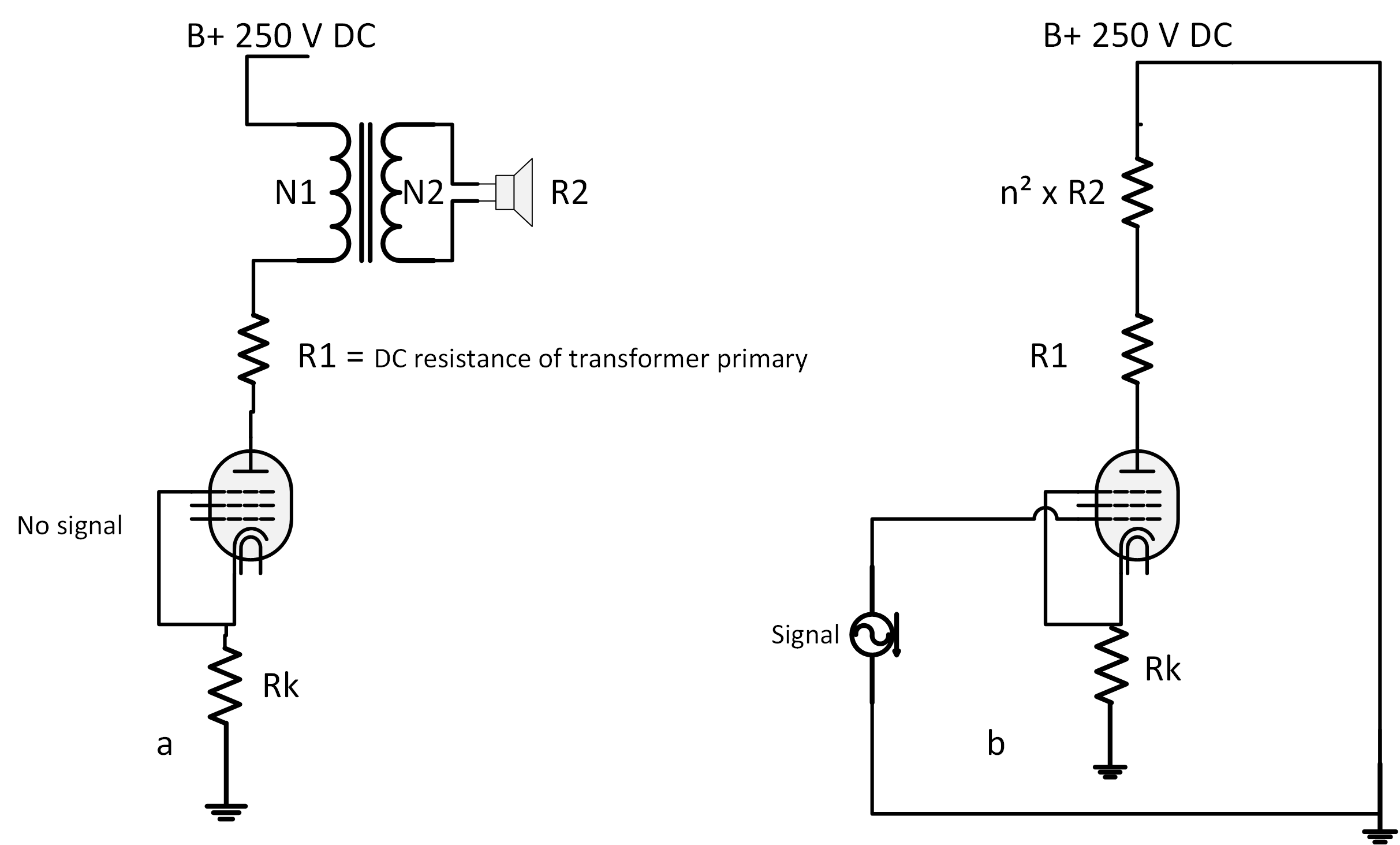
When no signal is present, the valve sees only the dc resistance of the primary winding ( actually half of the total primary winding in a push-pull stage, at least in a class B stage). However, as soon as ac signal is present, the valve will see the dc resistance of the primary turns of the transformer in series with the reflected impedance from the load. Let me take an example, and for this example II will go back to the single ended stage, it works in the same way, just imagine that this is half of the push-pull stage seeing half of the transformer:

Let us say that the DC resistance of the primary winding is 200 ohm (R1)( it is a very poor transformer,but it only to show how it works); drawing “a” above show the no signal condition, the valve will only see the resistance of the primary copper winding, presented by R1 in the drawing. This is the resistance used to draw the DC load line, quiescent condition, with no signal present.
Once the ac signal is present there will flow AC currents in the transformer and the valve will not see only the 200 ohm, but also the reflected secondary impedance n² x R2 in series with it. If we set “n” to be 14 and the loudspeaker to be 8 ohms n² x R2 = (14) ² x 8 the reflected impedance is 1568 ohms. The total AC load the valve see is then 1568 + 200 = 1768 ohms.
Therefore, the DC load presented to the valve is 200 ohm, and the AC load is 1768 ohm.
We have not taken the winding resistance of the secondary into consideration in the formula, but it is reflected the same way as the loudspeaker impedance.
If we look at the data for a real transformer above, the DC resistance of the primary winding is only 96 ohm, and the resistance for the secondary will always be less than this, the normal tolerances among different valves (ri variation) is much larger than this. Therefore, in the real world it will not make any noticeable difference whether it is included in the calculations or not, except when we want to draw the DC load line, or off course if we are designing a transformer, but that is not what this article is dealing with.
We also have other losses in an output transformer, among them are:
Power losses because of setting up the magnetic field, these are hysteresis loss and eddy current loss, these are among the main reasons that a transformer for a SE amp must be a lot larger than for a P-P amp, with similar specifications. There is some more, losses for the low and high frequency range, these depends on the physical construction and design of the transformer, but none of them will be dealt with in this article.
Triode Push-Pull stage:

Figure 1
The push-pull output stage will act different in class A than it would in class B, when it comes to how the transformer is used, with class AB somewhere between these. Let us look at class A operation, but first another drawing to explain things.

This drawing is a so-called equivalent circuit to the output stage. The following are new to this drawing:
| ri | Internal dynamic resistance of the valve (rp in us) (AC value) |
| Rp | Primary copper resistance |
| Rs | Secondary copper resistance |
| Ns | Secondary turns number |
| Np | Primary turns number |
| Zs | Secondary load impedance |
0.5 x Np is the turns for half of the primary (a to a), of the transformer and, 0.5 x Rp is half the total copper resistance of the primary, it will be important later. Everything to the left of the black dots are internal to the valve itself.
Let us first look at what happens in a class A output stage:
In a class A stage both of the primary turns (0.5 x Np) will conduct at the same time, but in opposite phase. That makes it a bit more complex, because the secondary windings will interact with each other, more about this in a later article. The impedance of the transformer presents to the valves will be:

Remember, both the prinary halves conducts curret at the same time:
We can make it a little simpler:
![]()
In addition, even simpler if we do not take the copper loss in to the calculation and this is the formula you will use in most cases:

The load (anode impedance) to each triode in class A will be, without copper losses:
![]()
Now to class B triode push-pull amplifier:
Here the primary transformer halves conduct the anode currents alternately. Each triode is conducting or blocking alternately, so here we have only one half primary conducting at the time.
The load to each valve, (because each triode sees only half the primary windings) without the math leading to it, is:
![]()
This is for the triode that is conducting, the other triode is blocking and has Za = ꝏ, but the anode voltage is still changing. The load impedances pr. Triode in class B varies between 0.25 times Zaa through Za, to infinity depending on the signal, or put in another way:
0.25 x Zaa < Za < ꝏ
Class AB lies somewhere between A and B. and the load impedance pr. Triode varies between:
0.25 x Zaa < Za < 0.5 x Zaa
Because the class of operation changes from A to B during one cycle of the signal.
We may say that the load that the transformer presents to the valves does not have a constant value for all values of current through the transformer windings. In addition, that goes for the internal AC resistance of the valve (ri) too.
This shows that the dynamic (AC) load line for an output stage actually never will be a straight line, it is in fact an ellipse, but we cannot use that for calculations, so we assume that the load is resistive and that gives us a satisfactory result, but that is not the subject here.
When it comes to selecting the load for a given set of valves, many different compromises have to be made, and selected. I recommend checking the manufacturer’s data.
Although I have presented the formulas above for a triode stage, they are also valid for a pentode output stage.
When specifying an output transformer for an amplifier we usually specify the load impedance wanted a-a (or you could use the turnover ratio), but we also must specify the maximum anode current you expect the output valves to draw.
There are a lot more to say about the design of push-pull power amplifiers, and transformers, but it is not the subject of this article. Among the things not covered are Composite load lines, B.J Thomson method of load lines, most favourable load and a lot of other stuff. Some of which will be the subject of a later article.

Thanks for explaining how an output transformer has no impedance in itself. My friend is thinking of purchasing an output transformer. I’ll tell my friend about how output transformers have no impedance so he can be prepared for that when he buys one.
Hi, and thank you for commenting.
It is the transformer ratio that gives you the needed primary impedance and the correct load for the valves, not the transformer primary in itself. The transformer you linked to has 8 k. ohms primary impedance if you use an 8 ohm load to the secondary side. So the ratio for this transformer is then:
n = √(Primary Impedance(R1)/Secondary load(R2)) = √8000/8 = 31.62
If you instead connected a 4 ohm speaker to the same transformer the load presented to the valves would be:
Primary impedance = (n) ² x secondary load => (31.62) ² x 4 = 3999 ohm, using the same transformer.
This is why we say that a transformer has no impedance of itself, it only reflects the secondary load impedance over to the primary side by the transformer ratio².