How to test an output transformer.
It is relatively easy to determine whether a transformer is defective or not, by using a multimeter. And if you are working with tube amps you may need to calculate the output transformer impedance especially when we have an old transformer or a transformer with unknown values, this can also be done using a multimeter and a signal generator.
B + denotes the high voltage of the amplifier.
IMPORTANT:
Disconnect power and let all the capacitors discharge before you begin. Remove the output tubes from the amplifier.
There are dangerous voltages in a tube amp, so be careful, check that there is no tension on the circuit by measuring the B +.
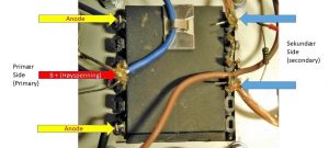
It is important to identify the correct wiring of the transformer before beginning. The primary side will have two lines if it is a “single ended” amplifier, 3 if it is also ultralinear. One wire is connected to B + and the other is in most cases connected to the anode of the tube. The UL wire will be connected to the screen grid on the output tube.
A push pull amplifier will have a minimum of 3 wires on the primary side, and 5 if it is ultra-linear. You need to find out which wires are what. Begin by finding out what is B +, it will be the center leader at pushpull.
I take this as a starting point for a push – pull transformer.
Connect the multimeter to both wires that go to the anodes and note the resistance value (ohms). Then connect the multimeter to B + and the line that goes to one of the anodes of the valve. Note the value and measure to the second valve if it is a push pull transformer. The readings from the B + to the valves should be about half of the measurement between the anode connections at push-pull, if the difference is great, it indicates errors with the transformer.
The resistance in the winding’s from the anode to the anode will be on the order of 10 to a couple of 100 ohms, the same applies from the anode to the B +, but about half the a-a reading. Readings of values more than 1 Kohm almost always indicate that there is a break in the winding’s. Readings below about 10 ohms indicate short between two or more of the winding’s.
Do a similar test on the secondary side (speaker side), the value here will be lower than the primary side, usually from 0.5 to 10 ohms because there will generally be fewer winding’s and a thicker copper wire used.
Also measure the resistance between the winding’s and earth, on the primary side there should be hundreds of Kohm , if there is a low value here, it indicates a short to earth . On the secondary side, we has to check if one side is connected to ground before doing the test, in some cases it can, if so, disconnect and check. The readings should then be as on the primary side.
In some cases, it may be a good idea to disconnect from B + as one may be fooled by the power supply when measuring on the primary side.
Finally test between secondary and primary side, a low value here (should be many Kohm ) indicates short circuit.
If the transformer fails in any of these tests is probably faulty and should be replaced, but there may be other faults with it even if these simple tests are not showing anything. If the transformer seems to be OK after these measurements, we know that it is not completely short-circuited or has broken, but if it still does not work as it should, we could use some more advanced methods to find out if there is something wrong with it. This means connecting a signal to the transformer and making some simple measurements, using a voltmeter that can measure the frequency we are going to use, or an oscilloscope. And do some simple calculations.
This method can also be used to find out some of the transformer data if it is unknown.
We can use another transformer as a signal source, this will give a 50 Hz (60 in the US) signal we can test with, but 50 Hz can be in the lowest layer as frequency so I prefer to use a signal generator that can provide 1 kHz signal with fixed amplitude.
Let me show you an example of how to do this, I’ll check an output transformer for an EL34 push-pull output stage. The drawing shows a transformer for push pull, with outlets for Ultralinear coupling, the picture shows a similar transformer but without UL connection.


We first check if the transformer is in order by measuring the resistance in the windings:


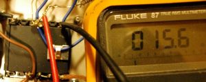
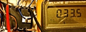
Here we measure between the points to be connected to the anodes on the valves, and get a value of 33,5 ohms, measurement from anode to B + gives 15.6 ohms on one winding and 15.3 on the other so the primary side seems like to be ok. Secondary side measurement (speaker side) gives us 1.2 ohms, and due to fewer windings and thicker wire, this is normal.
This transformer thus seems to be fine, based on windings resistance, but we still do not know Transformer conversion ratio and thus the load impedance it presents to the valves.
I will now try to find the load impedance using a signal generator.
We should be aware that a transformer does not have its own impedance when using it in an output stage, it has only one conversion ratio, and the actual impedance it presents to the output tubes depends on the value connected on the secondary side. See my article: Impedance matching of loudspeakers to output tubes
When we want to check a transformer, we can connect the signal to either primary or secondary, it does not really matter, but we must be aware that N1 is the winding on the primary side and N2 is the winding on the secondary side in the formula, whichever side we choose to connect the signal to when measuring the voltage. I’ve connected the signal source to the primary side in the measurements I’ve made here.
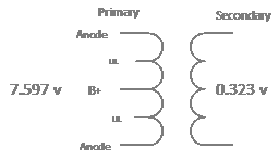
I connect the signal to the primary side (anode – anode connections), check this signal with the meter and note the value 7.597 volts rms.

I do the same on the secondary side and note the value 0.322 volts rms, I round up and use 0.323 as value.

We are looking for a ratio so it does not matter if you read the value in volt rms, p-p or whatever, as long as you use the same type of reading on both the primary and secondary sides.
The readings entered in the schematic will be as follows:

Now, we can calculate the transformer’s impedance on the primary side, ie the load it will give to the output valves with a given load on the secondary side.
We know that the turnover ratio of a transformer is:
n = N1 / N2 = V1 / V2 = √ (R1 / R2)
Where:
N1 = The quantity of turns on the primary side

N2 = The quantity of turns on the primary side

V1 = The voltage on the primary side

V2 = The secondary voltage

R2 = Secondary side load impedance ( speaker )

R1 = The effect of R2 reflected over to the secondary side ( anode load )

n = Conversion (turnover) ratio of the transformer
Based on what we know, we can calculate the transformer’s turnover ratio:
n = V1 / V2 = 7.597 / 0.323 = 23.52
We assume that the speaker’s impedance (load) is 8 ohms, which is quite common, this becomes R2 in the formula.
n = √ (R1 / R2) now let us solve this formula for R1:
R1 = (n) ² x R2 => ( 23.52 ) ² x 8 = 4425 ohms.
The measured transformer will thus present a load (anode to anode) of 4425 ohm (4.4 Kohm) to the valves at a speaker load of 8 ohms.
The method used here only gives us the transformation ratio, it does not tell us anything about the perfromance of the transformer. If we want to find out some more about that we will have to do some other measurements on the frequency characteristics and primary/secondary inductance among other. We should also then feed the transformer primary from a higher impedance source, the low fraquency generator used above is a low impedance source and will not give us the correct perfromance data. See also the article: A bit about Single ended stages, and output transformers.
In these measurements and calculations, I have used an output transformer for push – pull, the principle is exactly the same at a “single ended” transformer, then you measure from B + to the anode and calculate in the same way.
If the transformer has multiple taps on the secondary side, we can use this method to find the conversion ratio for one tap at the time, The multiple taps will give you a transformer that can be used to present multiple loads to the valves, or it can be designed to be used with different speaker impedance’s.


Excellent information! I have a Mesa-Boogie that has two 12AX7 tubes each in a push pull configuration as drivers to the six output tubes. The problem is the voltages are off on one push-pull section. The sound output is low and distorted. This will help me determine the problem!