Valve formulas part 1. Common Cathode
When we want to design a valve stage, we normally use the characteristic curves to obtain the data we need, and then use some formulas to calculate the needed values.
All formulas for valves are based on based on the assumption that the valve itself is a linear and perfect device, and all the so-called constants really are constant, neither part is true.
The formulas will give us a result that is good enough for most purposes. We will in most cases operate over a small part of the curve, so it will be almost linear, and since the tolerances for most valves is around 20%, any calculations, and use of curves, will give us approximate values.
In this article I will not show how to derive the formulas.
abbreviations used:
| Av | Voltage amplification |
| Ai | Current amplification |
| ra | Dynamic output resistance |
| gm (S) | Transconductance , mutual conductance (S – steilheit, steepness in Norwegian and German) |
| Z | Impedance |
| µ | Amplification factor |
| ri | Anode Internal resistance AC (rp, ra) |
| Ri | Anode internal resistance DC |
| D | Durchgriff ( Anode penetration factor) |
| V (U) | Voltage, (U is used for voltage in some of the drawings and formulas) |
| fn | Lowest frequency calculated (-3dB point) |
Let us start with the configuration that is most used:
The common cathode:

The voltage amplification for the stage (V1) is, (use the one that you want):
Va and Vg is the Ac (signal) voltages.
gm, for the valve given by the manufacturer is a static value, which is with no load. The value for gm we should use for calculations is the dynamic value, that is, off course, with load.
I assume that the load to the first stage, Rg2, (the grid resistor for the next stage), has such a so high value that it can be omitted. If not it must be calculated as a parallel resistor to Ra, and the result used in the formulas instead of Ra.
When a triode valve is connected to HT through an anode resistor Ra, which is the normal working conditions, we get an actual gm, called dynamic gm, which is:

And the amplification under working conditions will then be:
![]()
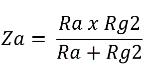
Where Za is the actual load to the valve. That is not only the anode resistor (Ra), but the parallel coupling of Ra and the load from the next stage, unless the load has a so high value that it can be omitted:

However, Rg2 in the formula may also be the input impedance of a power amplifier, tube amps typically around 100 Kohm, and SS around 10 Kohm. Or it may be any other load presented to the valve.
The output resistance of the stage is, approx.:

Where Ra is the anode resistor.
Cathode resistor (Rk) is:

The first one is what we really want; the voltage over Rk is the bias voltage for the valve Vg.
Now let us look at the capacitor, Ck, this capacitor not only sees the cathode resistor, but also the anode resistor and the valve resistance, Ri, in series, remember the HT is ac ground through the capacitors in the power supply. The value of these resistors are also influenced by the gain of the valve itself, so the resulting resistance, rk, must be calculated as:

However, the capacitor off course also sees the cathode resistor in parallel with rk, so:

And, finally the capacitor Ck:

Where fn is the lowest amplified frequency, -3 dB point.
Sometimes we want to omit the cathode capacitor; this gives some feedback and will therefore reduce the amplification. So, amplification without Ck is:
![]()
Alternatively, if µ is much larger than 1, which it will be in most cases:

The common cathode amplifier described above is the most common of all valve configurations, with or without the cathode capacitor, Ck, when we remove Ck we actually introduces some feedback to the circuit. In the next article I will look at some feedback configurations of the common cathode stage.


Comments
Valve formulas part 1. Common Cathode — No Comments
HTML tags allowed in your comment: <a href="" title=""> <abbr title=""> <acronym title=""> <b> <blockquote cite=""> <cite> <code> <del datetime=""> <em> <i> <q cite=""> <s> <strike> <strong>